Basys-Robot
An auto-seek pilot with obstacle avoidance and Bluetooth control based on Digilent Basys3 and Verilog.
Motivation
Background
With the development of artificial intelligence, robots of various types have been gradually entering people’s lives, which brings much convenience. Inspired by the commercial cleaning robot in people’s houses, this project uses Digilent Basys3 and some other peripherals to build a Basys-Robot based on Verilog HDL.
Specification
This project has a wide potential range of use cases. It can be applied to do the housework or search for missed objects. Besides, with additional improvement, it can have more advanced functions to do more complex jobs.
The main functions of the Basys-Robot are listed below.
- Remote Control: It can be controlled remotely with Bluetooth.
- Tracking: It has the function of visualized identification, thus it can identify a specific object and track it automatically.
- Self-adaption: During its working process, it can adjust its speed and avoid obstacles.
Hardware Implementation

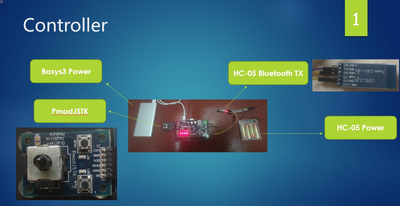
The whole system can be divided into two modules: transmitter and receiver, which communicate with the protocol of Bluetooth. The transmitter receives the control information from the joystick and transmits it to control the motion of the robot. The receiver simultaneously obtains the information from the transmitter, the ultrasound sensor and the camera. Based on this information, it determines the motion of itself.
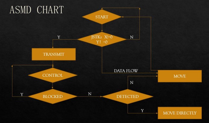
The algorithmic state machine (with datapath) chart is shown above. Once the system enters the state of START, it first decides whether the received position of the joystick deviates from the center. If not, it returns to the state of START, otherwise, it enters the state of Transmit and then transfers to the CONTROL state quickly. It loops until the absence of a BLOCKED signal. Then the system enters the state of DETECTED. If it detects the object that needs to be tracked, it moves towards the object, otherwise, it follows the control information from the joystick.
Software Design
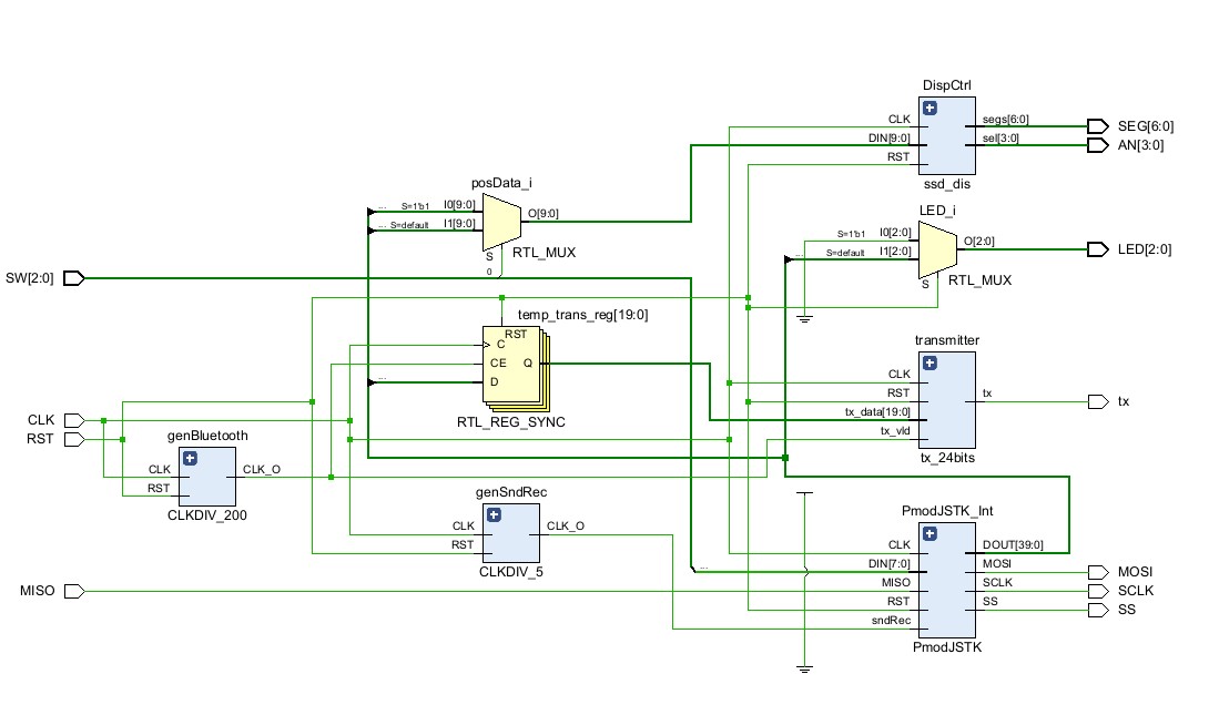
The module of the joystick is shown above, PmodJSTK reads the 20-bit data of the joystick and transmits it to the Bluetooth serial by the register buffer, which receives the position information with a baud rate of 2400. It also adds a 4-bit high pulse signal at the end. As the HC-05 Bluetooth transmits a signal 8-bit one time, the 24-bit data passes a converter module before sending it to the Bluetooth.
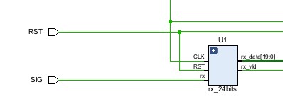
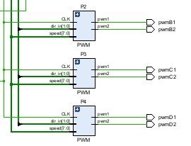
Once the receiver gets the 8-bit HC-05 Bluetooth data, it reads them into a 20-bit register buffer and a 4-bit read pulse register named VLD. If the receiver detects the descending edge of VLD, it confirms that the current frame is already read, the data in the register will be output to the x and y controller register.
The x controller determines the directions of the motors to control the rotation of the robot, while the y controller determines the velocity of the motor, which is decided by the duty cycle of PWM signal.
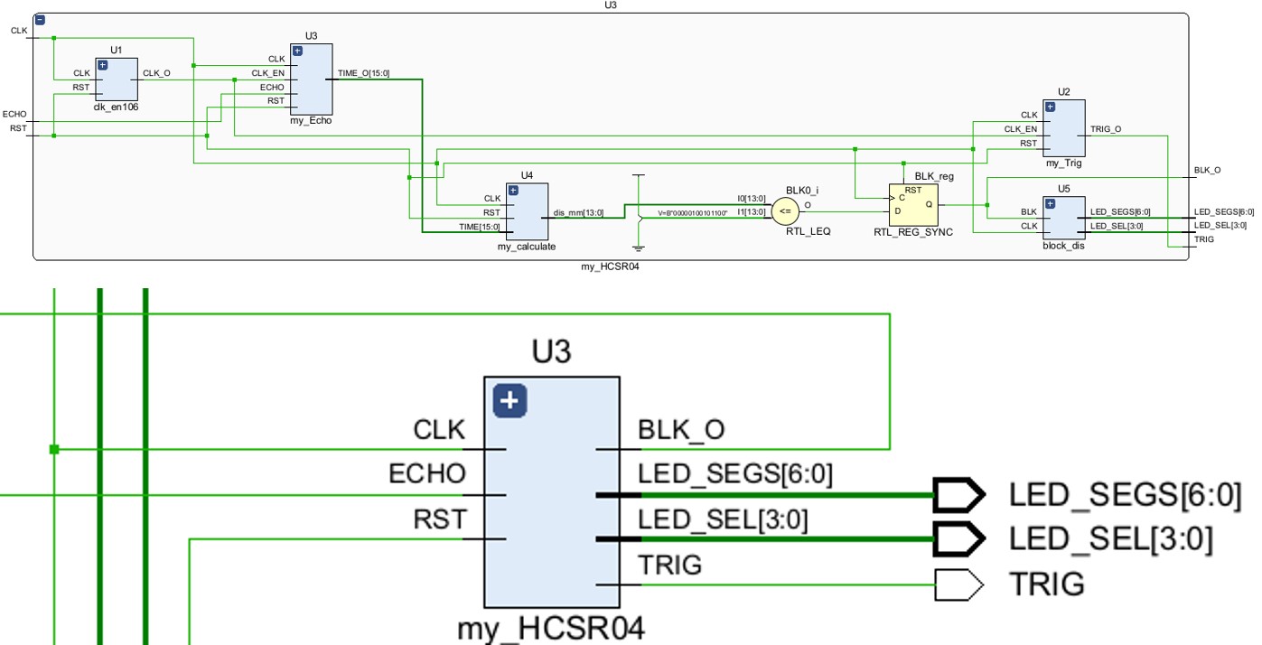
The HC-SR04 Bluetooth module needs a lower frequency to trigger and sample, thus we divide the main clock source to get a 1 MHz clock of this module. The functions of each sub-module are listed below:
- my_trig: Produce short pulse signal from the clock source.
- my_echo: Analyze the received pulse from the HC-SR04.
- my_caclulate: Calculate the distance of the obstacle.
- block_dis: Decide whether the Basys-Car is blocked meanwhile displaying the result to the LED.

The object detection module mainly relies on the communication with ov7670 camera. The core sub-modules include
- MMCM clock division: We generate two clock sources. The 25MHz clock is used in frame buffer, address generation and VGA signal control and synchronization.
- VGA: Read 12-bit data from the frame buffer and generate a 3-channel VGA signal with horizontal and vertical synchronization signals.
- Ov7670 controller: Communicate with the camera by \(I^2C\).
- Camera Capture and Address Generation: According to the resolution rate and sequence of ov7670, it reads 8-bit parallel data and generates the corresponding address, then stores them into the frame buffer.
- Frame Buffer: Use the IP core Simple Dual Port RAM in Block Memory to read and write the data into the RAM.
Once this module gets a full frame of data, it reads from the RAM and outputs it to the VGA, which displays as below:
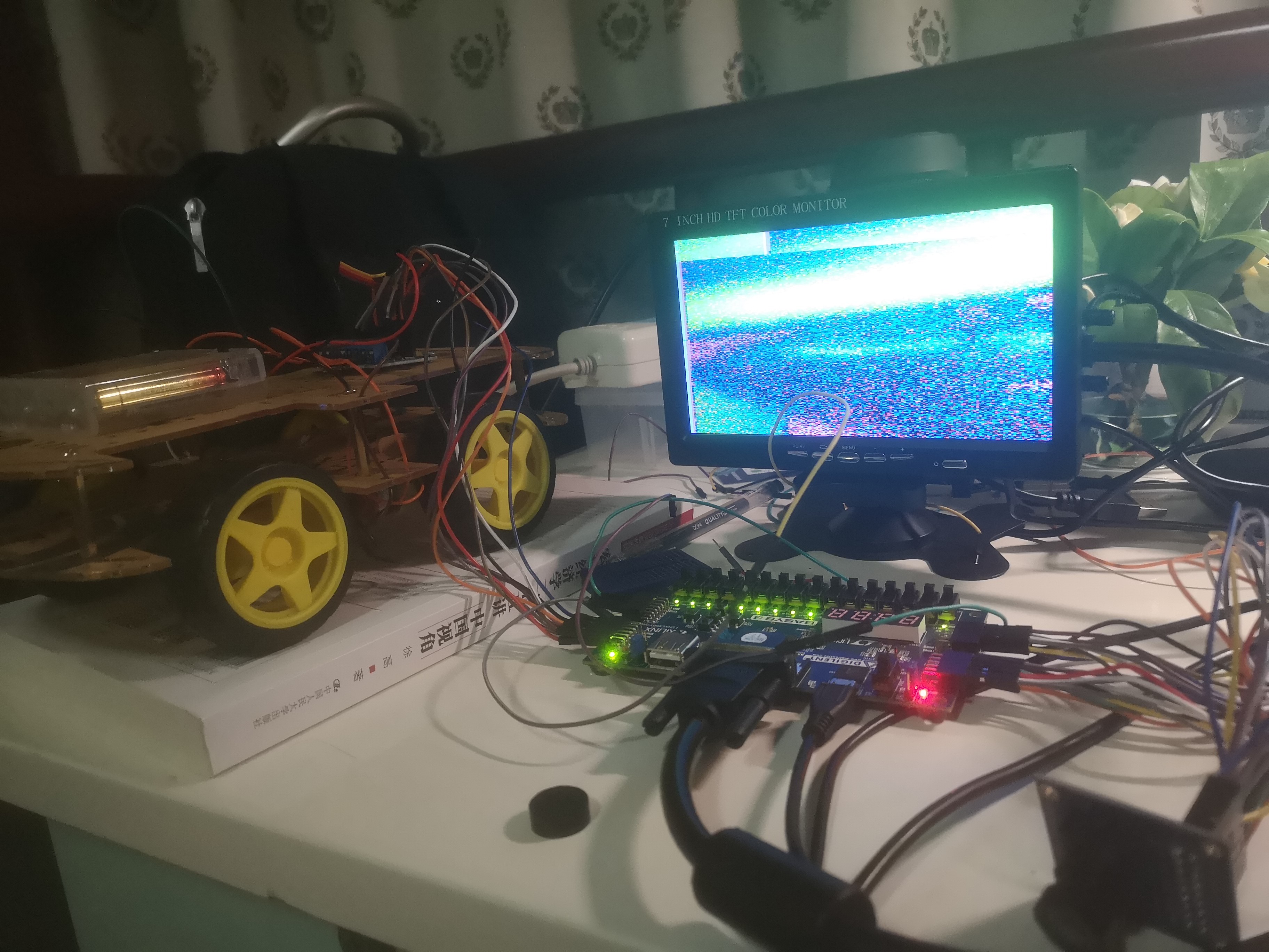
Actually, due to the performance restriction of the ov7670 camera, it has an inferior ability to capture distant objects, accompanied by too much noise and distortion. Thus, we consider identifying close objects, for example, human’s hand.
In our test, we find that compared to the background color, when a human’s hand appears in front of the camera, the highest bit of the b-channel of VGA is low, while the third bit of the r-channel is high. Therefore, we can use these two features to identify human’s hand.
However, as the 100MHz clock is too fast, identifying objects instantaneously may lead to larger errors. To do it more accurately, we need to observe the timing graph of ov7670.
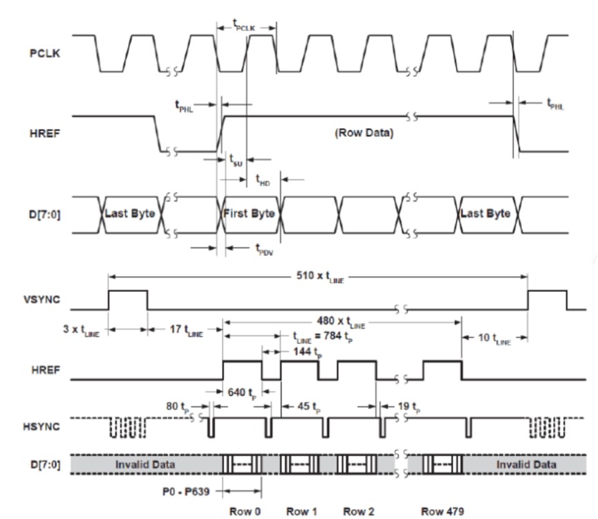
As shown in the figure, the data are transmitted with the PCLK clock, when the HREF signal rises, it reads a row of data with 640 bits. Before the two rising edges of VSYNC, there are 480 HREF signals to input each row of data.
Inspired by this, we set a timer with the same PCLK clock once we detect a descending edge of VSYNC. When the next VSYNC is detected, decide whether the timer reaches the threshold.
System Result
Resource Usage


System Overview

Display
The whole codework of this project is published on GitHub. See here.